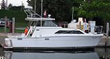
I didn't think to document the job until right after I started, so I went and got a (crappy) "before" photo from a sistership. Note the original rubber bellows leading up into, and the bypass muffler coming out of, the mother of all fiberglass tees. I know everyone who owns a tricab has worried about what happens when that bellows or hose clamp gives it up. This is the port side, looking aft.

Here is a picture right after I started. The factory rubber bellows and idle bypass muffler have been removed. As you can (maybe) see, there is a bronze tube that extends into the boat. The bellows are protected from abrasion against the metal tube by means of the no-wire rubber hose seen here. Anyone who would attempt to remove this hose and re-use it, please send cash in the amount of two hours of your labor to my account at Beacon Marine. Cut it off and buy new. Not only is it faster, in the confines of the bilge, it is even possible. I measured the vertical tube, and it protrudes to darn near the water line of the boat. I presume that I have just mis-measured, and that it actually it does extend above the water line. It would make no sense to do otherwise. The point is, all you tricab owners can sleep a little easier than you might have been.

Here is a picture of the exhaust eductors, or clamshells, after sandblasting. Water enters (in this view) from the bottom. That gap between the cones and the tubes lines up with the center of the vertical tube that goes up into the boat. After water enters the inlet tubes of the eductor, it is accelerated by their cone shape. The exit tubes in the eductor are larger than the aft (small) end of the inlet tubes. Once the boat is moving, the accelerated water helps suck the exhaust out of the vertical tube and eject it through the exit tubes. With the exception of the exit tubes, the whole affair is cast in one piece.

Here is a fish-eye view of the clamshell mounting plate. Visible is the bottom end of the tube that extends up into the boat. The inlet and exit tubes, with a gap between them, line-up under the brazed tube. A genuine craftsman brazed the plate to the tube.

I don't care for plywood backing plates. I made the exhaust backing plates (and all of the backing plates for my new seacocks) from 1/2" fire-retardant fiberglass sheet. I had them cut at a local granite countertop place for about $100 (plus material). I didn't bust any blades, I didn't inhale any fiberglass, and everything is plumb, level, and square. Here is the after-cutting picture for one of the two sheets that I had cut. The rectangles in the upper-right are shaft strut backing plates. Assorted seacock backing plates are also shown.

Every component of the exhaust system was removed, cleaned, inspected, and either refurbished or replaced. The plywood backing plate was the most fun to remove. Once everything was removed, sanded, degreased, etc., it was time to install new components. Well, not exactly. I knew it would be difficult to get the bolts that attach the external bronze plate to the internal backing plate to line-up correctly going through the existing screw holes in the hull. I countersank said holes through the hull both inside and out, so that the filler material would be mechanically keyed into the hull, as well as have increased bonding area. I then injected them with filled epoxy. At least I tell myself that I did it that way, instead of trying it and then realizing that the holes would never line-up. Then I clamped the outside plate in place and drilled new holes up into the hull and through the fiberglass backing plate.
Here is the backing plate being attached to the boat. Note the black tape around the bottom of the metal tube. It serves two purposes. It keeps the metal from being glued to the boat, and it centers the tube within the existing hole in the boat. Not seeing the point of bonding fiberglass to fiberglass with 4200 or even 5200, I used epoxy. When the next civilization rises after Armageddon, this piece of my boat will still exist. I used 3" bronze screws to attach the external clamshell support to the boat. Note in a picture below how little of the screw sticks out of above the fiberglass backing plate, especially on the chine side. The only issue with using epoxy was, what if there was a worm hole in the epoxy and it leaked after installing it? I made sure there weren't any. A year later, it doesn't leak.

Moving right along, the external plate (and integral vertical tube) have been screwed in place with new hardware. Before installation, the outside end of each screw hole was chamfered where it enters the fiberglass (at the interface between the top of the outside backing plate and the bottom of the hull). This allows extra sealant to surround the screw where it enters the boat. It forms a truncated funnel shape that prevents a "dry" area from occurring in the sealant should the screw be touching the side of the hole. This is a shot of the bellows buffer, or bushing, which I installed next. After all, to reassemble, reverse the disassembly, right? If you would have done it this way, send me four hours labor as described above. Note that the upper edge was chamfered in order to protect the inside of the bellows.

Once the liner was over the metal exhaust tube, I couldn't push the bellows over it. No way. Nada. Nothing. Not a chance. So how was it possible to push the liner onto the exhaust tube after if had been squeezed into an even smaller diameter by the bellows?
You need to do this. The bellows assembly is resting on top of the vertical exhaust tube.

I cut a piece of wood to fit within the bellows. The wood rests on top of the no-wire hose, and acts as a washer. A piece of threaded rod extends from the top side of the wood to the outside of the boat. As the nut on top of the wooden washer is turned, it draws the bellows and no-wire hose down onto the metal exhaust tube.

The process is made much easier if you use a flex-head ratcheting box end wrench.

And here is the outside. A little water on the rubber/metal interface and a few cranks with a ratcheting box end wrench and voila!

About those clamshells.... The outlet tubes are just copper tubing. The are attached at the factory by screwing through the clamshell, into the (thin-walled) copper tube, i.e., the screw heads protrude into the water, and there is about one thread in the wall of the copper tube. Refer back to the image of the sandblasted clamshells. After three decades, that attachment was shot. Some of the copper tubes are not your everyday plumbing size. I reversed the attachment scheme, and just re-used the tubes. I tapped the clamshells 1/4-20 where the old screw used to be, then drilled an extra access hole in each tube, 180 degrees from the factory hole, to allow the screwdriver to reach a screw head that is on the inside of each tube. Once installed, I sanded the screws flush with the outside of the clamshell. Here are a few of the screws that I removed, and one of the replacement screws.

Almost done....
Now its time to attach the clamshell. So you want new 5/8" bolts to replace the originals, but only 3/4" is stocked? Here was my solution. I screwed the longer bolts into a piece of 5/8" particle board, and let the belt sander do its thing.


Outside all done:

A view from the inside, ready for paint. I applied 4200 or 5200 around the edge of the backing plate to fair it into the surrounding area. Doing so makes things easier to clean (yes, the tail of that tie-wrap has since been trimmed).

Overall, this job was a very rewarding job that went off without any real surprises. I took the opportunity to upgrade the hose clamps -- T-bolt on the bellows, and the embossed-female-thread-type, i.e., clamps that did not have the female thread cut out of the clamp, on everything else. The bellows that I removed cleaned-up quite well. They had no visible defects. They were neither cracked nor dry rotted. Same for the bypass muffler. Since I could find replacement bellows, I changed them. I reused the bypass muffler because a). it looked fine, and b). I couldn't find a replacement.